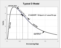
The output voltage function for D model sensors includes a near side region where the voltage rises with increasing distance, an optical peak region, and a far side region where the voltage output decreases with increasing distance. Operation in the near side region gives high sensitivity with limited operating range. Operation in the far side region gives moderate sensitivity with greater operating range.
Tip Details (E=Fiber Bundle Diameter):

Reflectance Dependent “D” Models — Probe Dimensions
| Model # | A (meters) | A Diameter (mm) | B (mm) | C (mm) | D (mm) | ß (°) | Minimum Unified Thread Sizes | Minimum Metric Thread Sizes | ||
|---|---|---|---|---|---|---|---|---|---|---|
| D6 | 0.91 | 5.1 | 12.7 | 6.35 | 38.1 | 0.81 | 0.16 | 30 | 6 – 32 x 1.0 UNC | M3 x 0.5 x 25 |
| D12 | 0.91 | 5.1 | 12.7 | 6.35 | 38.1 | 0.81 | 0.51 | 30 | 6 – 32 x 1.0 UNC | M3 x 0.5 x 25 |
| D20 | 0.91 | 5.1 | 12.7 | 6.35 | 38.1 | 0.81 | 0.51 | 66 | 6 – 32 x 1.0 UNC | M3 x 0.5 x 25 |
| D21 | 0.91 | 5.1 | 12.7 | 6.35 | 38.1 | 0.81 | 0.51 | 30 | 6 – 32 x 1.0 UNC | M3 x 0.5 x 25 |
| D47 | 0.91 | 5.1 | 12.7 | 4.6 | 38.1 | 1.6 | 1.16 | 30 | 8 – 32 x 1.0 UNC | M4 x 0.7 x 25 |
| D63 | 0.91 | 5.1 | 12.7 | 6.35 | 38.1 | 3.18 | 1.59 | 66 | 8 – 32 x 1.0 UNC | M4 x 0.7 x 25 |
| D64 | 0.91 | 5.1 | 12.7 | 6.35 | 76.2 | 3.18 | 1.59 | 30 | 8 – 32 x 1.0 UNC | M4 x 0.7 x 25 |
| D100 | 0.91 | 5.1 | 12.7 | 6.35 | 76.2 | 3.18 | 2.54 | 30 | 1/4-32 x 1.0 UNEF | M6 x 1 x 25 |
| D125 | 0.91 | 5.8 | 12.7 | 6.35 | 76.2 | 3.96 | 3.18 | 30 | 1/4-32 x 1.0 UNEF | M6 x 1 x 25 |
| D169 | 0.91 | 6.6 | 15.2 | 7.87 | 76.2 | 4.76 | 4.32 | 30 | 5/16 – 32 x 1.0 UNEF | M8 x 1.25 x 25 |
| D170 | 0.91 | 6.6 | 15.2 | 7.87 | 76.2 | 4.76 | 4.32 | 25 | 5/16 – 32 x 1.0 UNEF | M8 x 1.25 x 25 |
| D171 | 0.91 | 6.6 | 15.2 | 7.87 | 76.2 | 4.76 | 4.32 | 25 | 5/16 – 32 x 1.0 UNEF | M8 x 1.25 x 25 |
| D240 | 0.91 | 8.6 | 19.1 | 9.53 | 76.2 | 7.92 | 6.1 | 25 | 7/16 – 32 x 1.0 UN | M12 x 1.25 x 25 |
Nominal Output Specifications:
Reflectance Dependent “D” Models
| Model # | Total Range mm | Near Side Range mm | Far Side Range mm | Near Side Resolution DC – 20 KHz microns | Far Side Resolution DC – 20 KHz microns |
|---|---|---|---|---|---|
| D6 | 1 | 0.2 | 0.8 | 0.25 | 1.5 |
| D12 | 2 | 0.25 | 1.75 | 0.06 | 0.6 |
| D20 | 1.27 | 0.12 | 1.15 | 0.01 | 0.1 |
| D21 | 2 | 0.25 | 1.75 | 0.05 | 0.8 |
| D47 | 5 | 0.3 | 4.7 | 0.04 | 0.9 |
| D63 | 3 | 0.15 | 2.85 | 0.013 | 0.3 |
| D64 | 6 | 0.2 | 5.8 | 0.03 | 1 |
| D100 | 10 | 0.4 | 9.6 | 0.03 | 1.9 |
| D125 | 15 | 0.4 | 14.6 | 0.013 | 0.9 |
| D169 | 20 | 0.5 | 19.5 | 0.05 | 5 |
| D170 | 30 | 0.9 | 29.1 | 0.08 | 7 |
| D171 | 50 | 9.5 | 40.5 | 2 | 7 |
| D240 | 76 | 14 | 62 | 3 | 8 |
