
| Option Code | Feature |
|---|---|
| A1 | (Analog) Provides temperature stabilized electronics for low drift and high accuracy. |
| A2 | Provides low speed analog output for muDMS sensors with USB output. |
| G1 | Additional output, DC coupled with 10x gain and adjustable DC offset. |
| G2 | Additional output, AC coupled with 10x gain. |
| G3 | Additional Output, Binary TTL Output, 0/5 volts. |
| H1 | High frequency amplifier for D models up to 200 KHz bandwidth. |
| H2 | High frequency amplifier for D models above 200 KHz to 1 MHZ bandwidth. |
| H3 | Provides RC models with a high bandwidth amplifier,DC – 200 KHz.Bandwidths up to 350 KHz can be specified. |
| +H1 | Additional output for D models with bandwidths up to 200 KHz. |
| +H2 | Additional output for D models with bandwidths exceeding 200 KHz up to 1 MHz. |
| +H3 | Additional high frequency output. |
| L | Low frequency amplifier (< 20 KHz), 100 Hz STD. |
| +L | Additional output with low frequency bandwidth (< 20 KHz), 100 Hz STD. |
| M | Digital display – DC volts. |
| N | Low Noise Amplifier – The amplifier is optimized to operate with highly reflective targets only. This cuts noise floor in half, thereby doubling resolution (For RC sensors only) |
| O | Provides an adjustable 0 to -4 VDC offset control. This feature is used to eliminate the DC offset from the sensor output, thereby increasing readout resolution. |
| P | Polynomial curve fit to specified calculation range. |
| Q | Connectorized AC/DC power adaptors and BNC outputs for 1, 2 or 4 sensors. |
| R1 | AMBIENT LIGHT REJECTION – STANDARD UNITS ARE SENSITIVE TO BROADBAND LIGHT FROM 400 – 1100 nm. WITH OPTION R1, INCOMING LIGHT IS BLOCKED FROM <800 to >900 nm. |
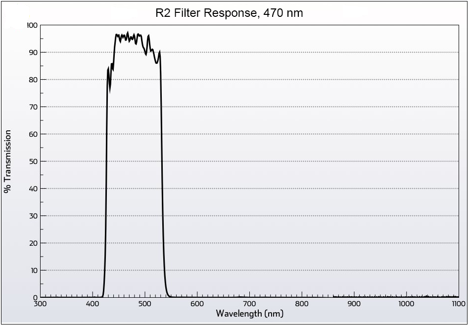
| R2 | BLUE LIGHT FILTER, 470 nm ±50 nm. |
| V | Provides sensor amplifier with 0 – 10 volt output. |
| Z | Additional Output with Linear Range Spanning 0 – 5 volts |