
Analog sensors are fast responding units ideal for relative motion measurements in dynamic applications:
- DC-20 KHz is standard
- DC-200 KHz or higher is optional
- DC-100 Hz provides best resolution
Standard analog units include:
- Electronics with 0 to +5 VDC output
- 3 foot long fiberoptic cable
Analog Output
Calibration charts are provided with each sensor tip giving the near and far side voltage output responses to distance. There are three ways to derive accurate distance measurements:
- within the bounds of the linear range, multiply sensitivity by the change in voltage output
- create a lookup table using the XY calibration data points
- use a polynomial curve fit to accurately map the sensor’s output function
These are reflective type transducers based upon detecting the intensity of reflected light. RC Model sensors have a pair of adjacent fiberoptic detectors in the sensor tip. Light reflected off the target follows two separate paths back to the electronics where a ratiometric calculation provides the distance measurement which is independent of varying surface reflectance; i.e., reflectance compensated.
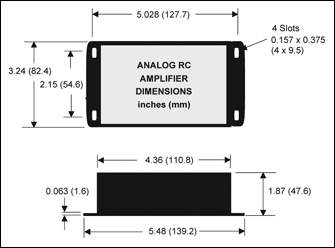
Amplifier Options
| Option Code | Feature |
|---|---|
| A1 | PROVIDES TEMPERATURE STABILIZED ELECTRONICS FOR LOW DRIFT/HIGH ACCURACY |
| G1 | ADDITIONAL OUTPUT, DC COUPLED WITH 10x GAIN and ADJUSTABLE DC OFFSET |
| G2 | ADDITIONAL OUTPUT, AC COUPLED WITH 10x GAIN |
| G3 | Additional Output, Binary TTL Output, 0/5 volts |
| H3 | HIGH FREQUENCY AMPLIFIER FOR RC MODELS UP TO 350 KHZ BANDWIDTH |
| +H3 | ADDITIONAL OUTPUT FOR RC MODELS WITH BANDWIDTHS UP TO 350 KHZ |
| L | LOW FREQUENCY AMPLIFIER (< 20 KHz), 100 Hz STD |
| +L | ADDITIONAL OUTPUT WITH LOW FREQUENCY BANDWIDTH (< 20 KHz), 100 Hz STD |
| M | DIGITAL DISPLAY – DC VOLTS |
| N | LOW NOISE AMPLIFIER (WITH HIGHLY REFLECTIVE TARGETS ONLY) |
| O | ADJUSTABLE DC OFFSET |
| P | POLYNOMIAL CURVE FIT TO SPECIFIED CALCULATION RANGE |
| Q | CONNECTORIZED AC/DC POWER ADAPTOR AND BNC OUTPUT |
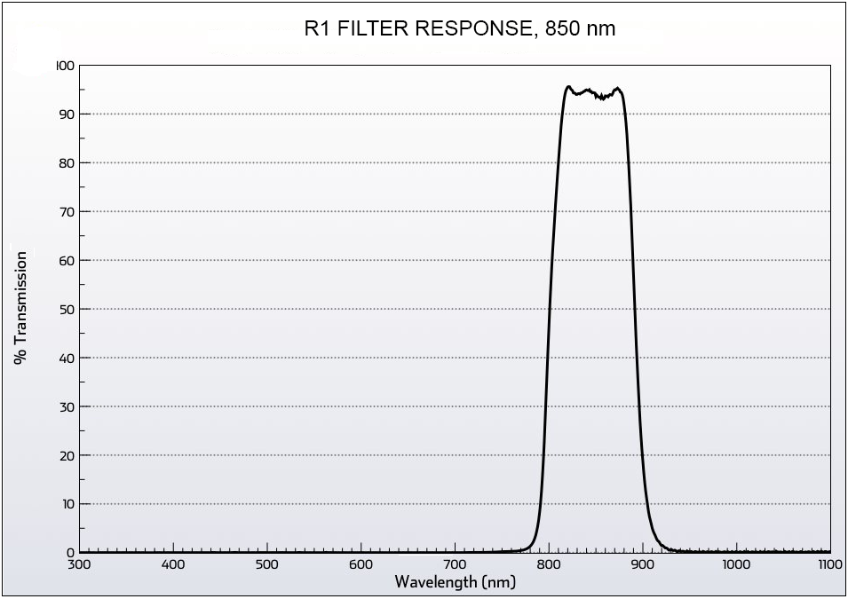
| R1 | AMBIENT LIGHT REJECTION – STANDARD UNITS ARE SENSITIVE TO BROADBAND LIGHT FROM 400 – 1100 nm. WITH OPTION R1, INCOMING LIGHT IS BLOCKED FROM <800 to >900 nm. |
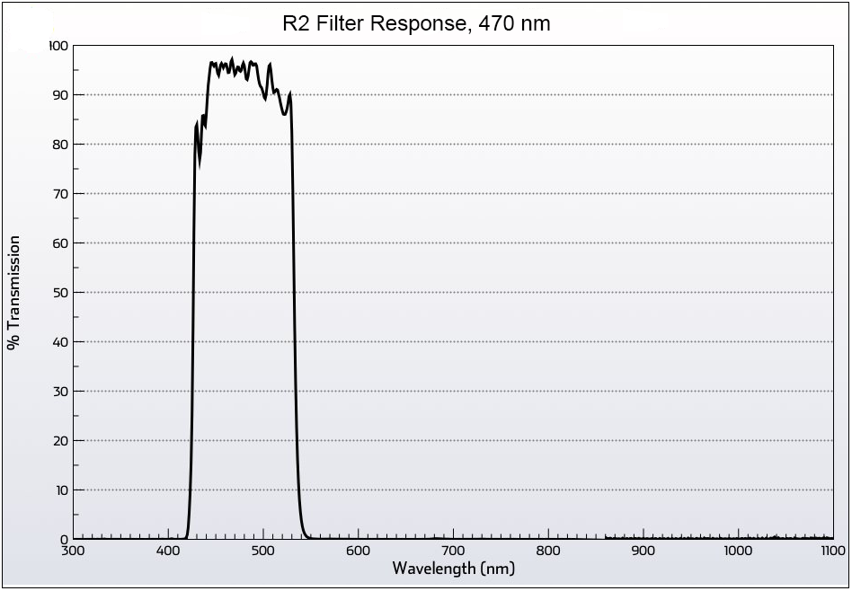
| R2 | BLUE LIGHT FILTER, 470 nm ±50 nm. |
| V | PROVIDES SENSOR AMPLIFIER WITH 0 – 10 VOLT OUTPUT |