
You can link to descriptive details on many of these options by clicking on the option letter in the table below.
The standard PHILTEC sensor package provides a stainless steel sensor tip, a 3 foot long fiberoptic cable sheathed with PVC over steel monocoil, and DC-20 KHz bandwidth amplifier or DMS signal processing unit as one integral unit with the fiberoptic cable potted into the electronic enclosure. Many options are available whereby the sensor tip, fiberoptic cable and/or the sensor electronics can be customized. Several options can be combined into one unit and specified using the following format: Model D100-BC1LT for analog units or Model DMS-RC100-BC1LT for digital units.
Important Note:
It should be realized that certain combinations of options are not achievable for all models. For example, it is not reasonable to expect to achieve high frequency response when combining replaceable tips with long fiberoptic cables and dark targets. Please consult with the factory when there are questions regarding such issues.
| OPTION CODE | FOR DMS | FEATURE |
|---|---|---|
| A (Analog) | No | Temperature Stabilized Amplifier Minimizes Long Term Drift |
| A (Digital) | Yes | Provides two additional 12 bit analog outputs for muDMS sensors with USB output. |
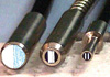
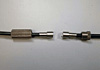 B B | Yes | Replaceable Tip Configuration – In-Line Connector (not available for D6 or RC12) |
| 2B | Y | Option 2B provides a 3 piece sensor system; amplifier, extension cable and probe. |
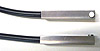
| B1 | Y | Replaceable Tip Configuration – Sensor Bulkhead Connector (not available for D6 or RC12) |
| Y | Connectorizes Sensor System With Single Channel Vacuum Passthru Hardware for 10 E-7 Torr (not available for D6, D12 or RC12) | |
 Bv133 Bv133 | Y | Connectorizes Sensor System With Single Channel Vacuum Passthru Hardware Mounted in a 1.33″ CF Flange, for 10 E-7 Torr (not available for D6, D12 or RC12) |
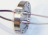 Bv2 Bv2 | Y | Single Channel Ultra-High Vacuum Passthru Flange for all D models (not available for D6 or D12). |
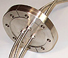 Bv3 Bv3 | Y | Single Channel Ultra-High Vacuum Passthru Flange for all RC models (not available for RC12). |
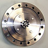 BvF BvF | Y | Multichannel High Vacuum Passthru Assembly for 10 E-7 torr (not available for D6, D12, RC12). |
| Bw | Y | Connectorizes sensor system with wrench tight in-line connector. |
| C1 | Y | Interlocking Stainless Steel, temperature range of -270° to +340° C. Maximum strength & temperature range, good flexibility. |
| C2 | Y | Silicone Rubber tubing, temperature range of -62° to +232° C. Maximim flexibility, no crush resistance, no tensile strength. |
| C3 | Y | Silicone over Nylon Wrap, temperature range of -62° to +232° C. 2 meter max. length, light crush resistance, non-metallic |
| C4 | Y | Corrugated Nylon Hose, temperature range of -40° to +104° C. Good flexibility, moderate crush resistance, MRI compatible, long lengths OK |
| C5 | Y | PTFE over SS Interlok, temperature range of -150° to +260° C, crush proof, liquid tight, vapor barrier protection, very poor flexibility. |
| C5i | Y | SS Interlok over PTFE – with PTFE inside the SS interlok, the jacket has a smaller diameter and is more flexible. Liquids can penetrate the SS interlok |
| C6 | Y | PVC over Nylon Wrap, temperature range of +10° to +107° C. Good for long lengths, light crush resistance, liquid tight, MRI compatible |
| C7 | Y | Translucent PTFE, temperature range of -150° to +260° C, MRI and vacuum compatible, poor flexibility, susceptible to ambient light interference. Opaque PTFE is available in limited sizes |
| C8 | Y | PVC Shrinkwrap, temperature range of +10° to +107° C. Small, light weight, very flexibile, no crush resistance, long lengths OK |
| C9 | Y | Annealed (semi-rigid) SS Tubing, temperature range of -150° to +800° C. Very poor flexibility, good for high temperature, high pressure, high vibration |
| C10 | Y | Silicone Over SS Interlok, temperature range of -62° to +232° C, liquid tight, flexible, crush proof |
| C11 | Y | Polyolefin Shrink Tubing, temperature range of -55° to +300° C, semi-flexible, liquid tight, thin wall vapor barrier, not crush proof. MRI, BIO and vacuum compatible, radiation resistant. |
| C12 | Y | Polyolefin over SS Interlok, temperature range of -62° to +300° C, liquid tight, semi-flexible, crush proof, vapoer barrier, vacuum compatible |
| C13 | Y | Furcation Tubing, PVC over Kevlar over PTFE, temperature range of +10° to +85° C, standard in the telecom industry because of the Kevlar members which prevent stretching. Ideal for small fiber sensors, D20 or RC20 and smaller. MRI compatible and liquid tight. Light crush resistance. |
| C14 | Y | Braided SS over PTFE, temperature range of -53° to +204° C, poor flexiblility, liquid tight, crush proof. Good for high pressure applications. Available O.D. sizes 0.312″ (with 2″ bend radius) and larger. |
| C15 | Y | Aluminum Flexible Conduit, semi-flexible and crush proof. Available O.D. sizes 0.51″ (with 4″ bend radius) and larger. |
| D | Y | Reflectance Dependent Output |
| E | Y | Glass fibers having light beam spreads of 25, 30 and 66° are used to produce Philtec sensors. The narrower beams give longer operating ranges. Standard Cable Lengths are 3 feet. For lengths exceeding 3 ft., specify Option E and give total Cable Length, 49 Feet Maximum (15 m).
|
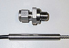 Fv1 Fv1 | Y | Low Vacuum Passthru for 10 E-4 Torr (1000 µPa). Provides Ø.375″ x 3″ L Solid Section on Fiberoptic Cable, Compression Fitting, and Stainless Steel Interlok Sheathing On Vacuum Side |
| Fv2 | Y | Low Vacuum Passthru for 10 E-4 Torr (1000 µPa). Provides Ø.250″ x 3″ L Solid Section on Fiberoptic Cable, Compression Fitting, and Stainless Steel Interlok Sheathing on Vacuum Side |
| Fv3 | Y | Low Vacuum Passthru for 10 E-4 Torr (1000 µPa). Provides Ø.500″ X 3″ L Solid Section on Fiberoptic Cable, Compression Fitting, and Stainless Steel Interlok Sheathing on Vacuum Side |
| G1 | N | Equips Sensor With An Additional Output, DC Coupled with 10x Gain and Adjustable DC Offset |
| G2 | N | Equips Sensor With An Additional Output, AC Coupled with 10x Gain |
| G3 | N | Additional Output, Binary TTL Output, 0/5 volts |
| H1 | N | Provides D models with a high bandwidth amplifier,DC – 200 KHz |
| H2 | N | Provides D models with a high bandwidth amplifierabove 200 KHz. Bandwidths up to 1.5 MHz (some models) can bespecified. |
| H3 | N | Provides RC models with a high bandwidth amplifier,DC – 200 KHz.Bandwidths up to 350 KHz can be specified. |
| +Hn | N | Designating +H1 or +H2 or +H3 provides a sensor amplifier with twooutputs: standard DC-20 KHz and a wideband output. |
| L | N | Equips sensors with a low bandwidth amplifier,DC-100Hz. Bandwidths as low as 10 Hz can be specified. |
| +L | N | Equips a sensor amplifier with two outputs: standard DC-20 KHz and a low frequency output, DC- 100 Hz |
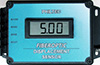 M M | N | Digital Display – DC Volts |
| N | N | Low Noise Amplifier – The amplifier is optimized to operate with highly reflective targets only. This cuts noise floor in half, thereby doubling resolution (For RC sensors only) |
| O | N | Provides an adjustable 0 to -4 VDC offset control. This feature is used to eliminate the DC offset from the sensor output, thereby increasing readout resolution. |
| P | N | Polynomial Curve Fit For Operation In Non-LinearRanges |
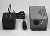 Q Q | N | Quick Disconnect AC Power Adaptor and BNC OutputConnector |
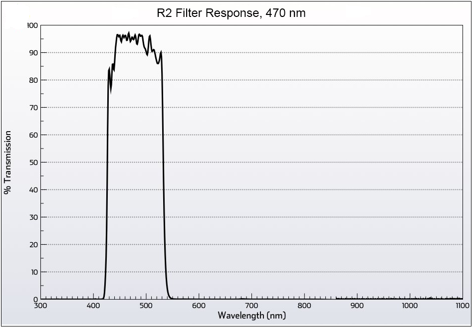
| R1 | Y | AMBIENT LIGHT REJECTION – STANDARD UNITS ARE SENSITIVE TO BROADBAND LIGHT FROM 400 – 1100 nm. WITH OPTION R1, INCOMING LIGHT IS BLOCKED FROM <800 to >900 nm. |
| R2 | Y | BLUE LIGHT FILTER, 470 nm ±50 nm. |
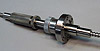
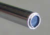
 S S | Y | Side-Viewing Sensor Tip |
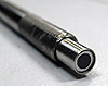
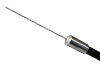 T1 T1 | Y | Customized Sensor Tip, Straight |
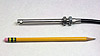
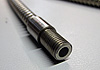 T2 T2 | Y | Custom Sensor Tip, Straight and Threaded, Standard Lengths |
| Y | Custom Sensor Tip, Non-metallic, Peek or Torlon | |
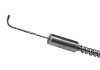 T4 T4 | Y | Simple Right Angle Tip |
 T5 T5 | Y | Square Body Right Angle Tip, Unthreaded |
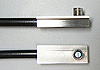 T6 T6 | Y | Square Body Right Angle Tip, Threaded |
 T7 T7 | Y | Special Tip Made To Customer Specifications |
| T8 | Y | High Temperature Tip, 350°C Max. |
| T9 | Y | High Temperature Tip, 450°C Max. |
| T10 | Y | High Temperature Tip, >500°C, Quartz Fibers. 800°C Max. |
| T11 | Y | Custom Sensor Tip, Metallic, non-magnetic, Brass or Aluminum |
| T12 | Y | Custom Sensor Tip, Invar (Low Expansion Coefficient) |
| V | N | Provides Sensor Amplifiers with 0 – 10 Volt Analog Output |
 W W | Y | Adds a sapphire window epoxied into the sensor tip. For high pressure or vacuum |
 Wb Wb | Y | Adds a sapphire window brazed to the sensor tip |
| Z | N | Additional Output with Linear Range Spanning 0 – 5 volts |